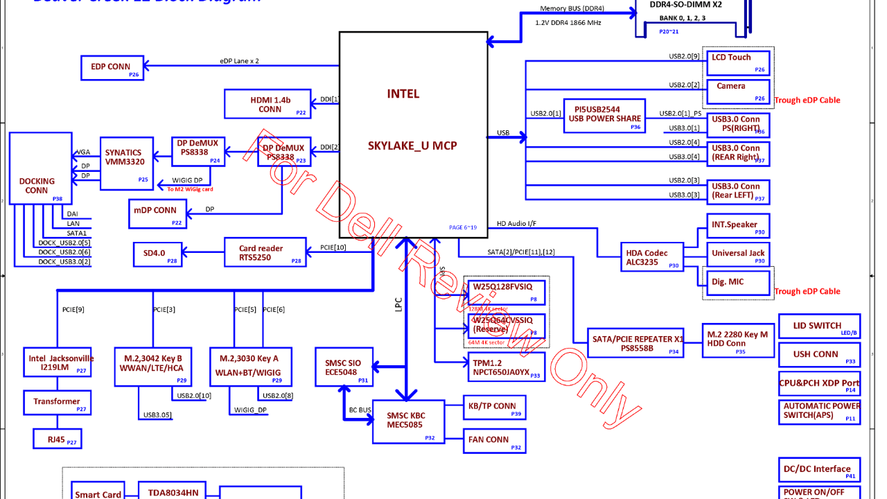
Dell Latitude E7270 and E7470 Schematics & Boardview
Dell’s Latitude E7270 and E7470 laptops, marked by their AAZ50 LA-C451P configuration, are popular choices for professionals seeking reliable performance. When issues arise, having access to the schematic and boardview files can be invaluable. These documents provide a blueprint of the laptop’s electronic circuitry, offering insights into component layout, connectivity, and functions. This article aims to demystify these resources, enabling even general users to tackle various repair tasks.
Are detailed diagrams showing the electrical connections and functions of a laptop. They outline each component’s relationship and signal flow, making them crucial for troubleshooting and repairing electrical faults.,on the other hand, provide a physical map of the motherboard. They help identify the location of components mentioned in the schematic, facilitating physical inspections, soldering, and replacements.
For Dell Latitude E7270 and E7470 owners, accessing the AAZ50 LA-C451P schematic and boardview can transform a daunting repair job into a manageable task. These documents can help diagnose issues ranging from power failures to malfunctioning hardware components. They’re especially valuable when dealing with no power situations, short circuits, and component failures.
Start by understanding the problem with your Dell Latitude. Is it not powering on? Experiencing overheating? Random shutdowns?Schematics and boardviews for the AAZ50 LA-C451P can sometimes be found online through forums, repair websites, or directly from Dell support for authorized service providers.Familiarize yourself with the symbols used in schematics (resistors, capacitors, ICs) and the layout in boardviews. Online resources or electronics books can be helpful. Use the boardview to find the physical location of the component related to the issue on your motherboard. The schematic will provide the electrical context, showing how the component interacts with others.With a multimeter, you can test components for continuity, resistance, and voltage as indicated in the schematic. This helps identify faulty parts. Once the faulty component is identified, it can be repaired or replaced. This might require soldering skills for component removal and replacement.


